2015
International Year of Light and Light-Based Technologies
Technical Aspects of Photography
Optics, Photometry, Sensitometry
It's an unfortunate fact of life that different manufacturers
have introduced the same features under different names. They stick to their own company jargon
in commercial literature and/or for the naming and marking of their optical equipment.
Here is an equivalence table, featuring "generic" terms on the first line:
Image stabilization can be done by the lens or by the camera sensor
(or both, if the manufacturer has designed systems which interact rather than fight each other).
The industry acronym for the latter is IBIS (In-Body Image Stabilization).
The issue was hotly debated in January 2018 when Panasonic released the GH5s, a more expensive version
of their flagship GH5 with a multi-format sensor with lower resolution
(for better low-light capabilities).
To do this, they had to forgo IBIS on the GH5s.
Panasonic justified that decision by explaining that IBIS may be redundant for the professionals so targeted,
who use tripods,
monopods, camera dollies, railtrack trolleys or gimbal stabilizers.
Most of us love IBIS, though, when those things are lacking...
Here's a quick list of some other fundamental concepts:
(2014-12-12) Basic characteristics of a lens
Focal length, thickness, aperture, focusing distance, reproduction ratio.
The basic characteristics of a lens are:
f = Focal length (from backplane to focal plane, if focused at infinity).
d = Distance between the principal planes.
A = Aperture (diameter of transparent disk on backplane).
Almost all lenses used in modern photography have an adjustable aperture,
so the "aperture" listed among the characteristics of a lens is really the maximal possible one
(iris fully opened and lens focused at infinity).
In addition to the above the following parameters are measured when a lens is focused
on an object at a finite distance:
D = Focusing distance (from object to focal plane).
r = Reproduction ratio (size of image divided by size of object).
Nikon
and other manufacturers may
indicate the position of the focal plane by a grove on the bodies of their cameras.
Without accessories (extension rings or bellows) D has a minimum value D0
corresponding to the normal use on the intended camera mount.
The maximum value of r is a function of that.
Opticians often use following variables which are functions of the above.
p = Distance from the object to the frontplane (outer principal plane).
p' = Distance from the image to the backplane (inner principal plane).
The above definitions imply that p = D-d-p'
The imaging equations for convex lenses are:
1 / f = 1 / p + 1 / p'
and r = p'/p
Eliminating p' , we obtain the relation between D and r :
p = f ( 1 + 1/r ) = (D-d)) / (1+r)
or f (1+r)2 / r = D-d
With extension rings (and/or bellows) of total length X, the maximum
value of the reproduction ratio is thus the solution in r of the above
equation with D = X+D0 which may be rewritten:
r2 + 2 r [ 1 - (X+D0-d) / 2f ] + 1 = 0
With 3 standard extension rings (12 mm, 20 mm, 36 mm)
X can have 8 different values (in mm): 0, 12, 20, 32, 36, 48, 56 and 68.
This equation has a (real) solution only when X+D0-d ≥ 4f
I recommend expressing the (positive) solution with the following
numerically robust form which is much more
convenient, on modern scientific calculators, than the equivalent
traditional quadratic formula involving square roots:
r0 = exp ( sinh-1 [ 1 - (X+D0-d) / 2f ] )
For example, published specifications for the
AF-S
DX Micro NIKKOR 40mm f/2.8G give f = 40 mm, D0 = 163 mm
and r0 = 1.0. The value of d is given by the equation:
d = D - f (1+r)2 / r = 163 - 40 (1+1.0)2 / 1.0 = 3 mm
(The intended/correct value is 0 mm for a perfectly color-corrected lens.)
The Nikon F-mount features a distance
of 46.5 mm from focal plane to flange. That should be added to the published nominal
length of this lens (64.5 mm when focused at infinity)
to obtain the distance (111 mm) from the image of infinity to
the front of the lens. Subtract this from the aforementioned 163 mm and you
obtain the largest extension size (52 mm) usable with this lens
(corresponding to the dubious case of photographing a backlit object
nearly touching the front of a lens focused at infinity).
To copy old-school 35 mm film slides on a DX sensor,
a reproduction ratio of about 1.5 is needed,
which would be achieved using an extension ring of 6.7, mm
with the lens on its fullest macro setting.
Using the thinnest commercially available extension ring (12 mm)
a reproduction ratio of 1.5 is obtained in the middle of the lens focusing range
(it's 1.7 at full macro).
(2014-11-28) Depth-of-field and hyperfocal distance.
Nearest and farthest distances in focus at an acceptable sharpness.
When an object point on the optical axis is in sharp focus,
the rays emanating from it converge to a single
point on the focal plane. If it's slightly out-of-focus, then they form
a cone whose apex is not on the focal plane.
That cone intersect the focal plane in a circle called the
circle of confusion.
When the diameter of that circle is small enough (typically defined as less
than 0.030 mm in 35 mm photography) the object is in acceptable focus.
When a print of prescribed sharpness is desired using different
formats of negatives, we are imposed a constant ratio between
the focal length and the diameter of the circle of confusion.
As a result, the hyperfocal distance is directly proportional
to the focal length or, equivalently, to the size of the negative.
Therefore, the larger the format, the tighter the depth of field.
Markus Keinath (article quoted in footnote) has observed that STF could be achieved
easily by firmware control of the iris of any lens, by opening (or closing)
the iris progressively during exposure
(during a period of time when the shutter is fully open).
This has never been done before, at this writing, and it would be a revolution for bokeh addicts.
An apodization filter may inhibit phase-detection autofocusing
(it doesn't interfere with contrast-detection autofocus).
(2015-05-03) A lens can be correct for more than one color:
2 colors (achromat) or 3 (APO, apochromat) or 4 (superachromat)...
The refracting index of glass (or any other medium) is subject to
dispersion, which is to say that
it varies from one wavelength of light to the next.
The different properties of an optical system at different wavelengths are collectively
known as color aberration (they translate into color fringes
observed on sharply contrasted parts on an optical image).
Mirrors are immune to it, lenses aren't.
Isaac Newton, who invented
the reflecting telescope, once stated that it wasn't possible to
build a refracting optical system free of color aberration.
It took thirty years to prove him wrong. Kinda. As early as 1729
(or 1733, according to some accounts) the amateur optician
Chester Moore Hall
figured out that different kinds of glass could be used to design an optical
system which forms identical images for red light and blue light
(because the index of refraction increases with wavelength in some glasses and decreases
in others.
Apochromatic Lenses and Beyond :
Solving what happens at both extremities (red and blue) of the visible
spectrum may diminish the problem in the middle as well (green) but
it doesn't quite solve it.
It would take more than 30 years before someone would design a lens
with the same characteristics at three colors instead of just two
(such a lens is now call apochromatic).
A true zoom lens ought to be parfocal
(i.e, its focusing distance remains stable when the focal length changes).
The older term varifocal is the general
term still used for systems with variable focal length which need not meet this requirement.
The general theory of parfocal zoom lenses was worked out in 1958
(using Chebyshev polynomials)
by Leonard Bergstein
(1928-2008) who happens to be my own "scientific grandfather" (as the second doctoral advisor of
Judea Pearl at the Brooklyn Polytechnic Institute, in
1965).
In 1955, well before completing his doctoral dissertation,
Bergstein applied for a patent covering some of his methods, which was granted in 1959
(US Patent 2906171).
(2014-11-27) Autofocus (powered focusing)
Reacting to distance to mechanically adjust the focus of a lens.
Nowadays, all autofocus cameras use passive focus detection which works by
analyzing the light received from the scene (as opposed to the
active sonar, most notably used with the SX-70 Polaroid camera,
which computes the distance by sending an ultrasonic signal and measuring the
time it takes to bounce back from the subject).
In low-light conditions, cameras may need to shine light from an auxiliary LED
for the autofocus to work properly.
(2015-06-12) Focus Breathing: When focal length varies with focus.
Just a minor issue in still photography. Critical in cinematography.
(2015-06-12) Darkening: Variation of aperture with focus distance.
Extreme in macro-photography (with extension tubes and regular lenses).
(2014-11-29) From large
formats to tiny sensors...
The crop factor is 43.2666 mm divided by the diagonal of the image.
The image sensor
used in many DX Nikon cameras
(D3300, D3400, D5300, D5500, D5600, D7100, D7200)
is an effective array of 6000 by 4000 pixels (24.2 Mp)
made by either Sony or Toshiba. It measures
23.46 mm by 15.64 mm (the pixel pitch is thus 3910 nm).
This has the same aspect ratio (3/2) as a 36 mm by 24 mm full-frame.
The crop factor is simply the scale between the two, namely 1.5345.
For dissimilar formats (different
aspect ratios)
the crop factor is defined as the ratio of the respective diagonals,
since the angular coverage of a lens of given focal length always pertains to
the diagonal of the image.
For example, the Panasonic Lumix DMC-ZS25 (labeled Lumix DMC-TZ35 in Europe)
has a sensor with a 4/3 aspect ratio
(6.08 mm by 4.56 mm).
The diagonal of the image is exactly 7.6 mm,
which translates into a crop factor of 5.693.
The native resolution is 4896 by 3672 (1242 nm pixel).
The big brother of the ZS25 is the Lumix DMC-ZS30
(a.k.a. DMC-TZ40) which has Wi-Fi, built-in GPS, a finer monitor and a
slightly
larger sensor. They both feature the same Leica superzoom:
LEICA DC VARIO-ELMAR 1:3.3-6.4 / 4.3-86 ASPH
The full-frame equivalent of this lens is advertised as 24-480 mm for
both cameras. For the ZS25, it would be more accurate to say 24.5-490 mm.
The APS acronym in two of the above formats stands
for Advanced
Photo System, the pompous name given to a large (technically misguided)
effort for mass-marketing a small format of film photography
(using economical 24 mm film)
starting in 1996,
just before the dawn of digital photography.
The production of new APS cameras ceased in 2004 and the manufacture
of APS film cartridges stopped completely in 2011.
Nevertheless, the format was a reference for a while.
Just enough time for the next generation of smaller digital sensors
to be marketed as "APS-C" format, which now stands (although
APS itself is all but forgotten).
APS allowed the film to record additional information besides the image
itself. Some of that could be printed on the back of the photos
and there were also standardized instructions to the photofinisher to crop
the image in one of the three following ways
(that could be overridden by special order, since the whole image was on film).
APS-H :
The whole image ("High Definition") 30.2 × 16.7 mm.
APS-C :
Cropped central part ("Classic")
25.1 × 16.7 mm
APC-P :
Horizontal view ("Panoramic")
30.2 × 9.5 mm
The machines of photofinishers used paper rolls with a uniform width of 4''
to produce 4x7'', 4x6'' and 4x11'' prints, respectively.
Throw-away cameras offered only a choice between "H" and "P",
as "C" seemed less desirable. (Ironically, that's the only extant
reference to "APS" now, although Canon's flagship DSLR once had an "APS-H" sensor,
back in 2001.)
(2015-06-11) Handheld Shots Require Fast Shutter
Make the shutter speed greater than the focal length in mm.
For example, with a handheld 300 mm telephoto lens, your shutter speed
should be 1/320 s of faster, or else you need a
tripod.
This traditional rule of thumb is only a starting point:
You may use a slower shutter speed if you have a very steady hand. Use
a faster one if you have less tolerance for blur and/or expect to produce larger prints.
This is all based on the acceptable blur induced by camera-shake
for a typical size of a finished printed image. With a smaller sensor,
the same print size requires an additional enlargement by
a factor equal to the crop factor.
All told, your shutter must be faster in the same proportion.
Another way to state the same thing is to say that the above rule-of-thumb
applies to the full-frame equivalent of the focal length
(which I like to call "reach" for short).
A 300 mm lens with a
Nikon DX camera (1.5345 crop factor)
has a a 460 mm reach and
must, therefore, be shot at 1/500 s or faster.
The aforementioned 1/320 s is just a little bit too slow
(the correction would be far more relevant with larger crop factors).
(2015-05-09) ISO scale of light sensitivity
The modern scale is the direct descendant of the ASA and DIN ratings.
In practice, the sensitivity scale we now use obeys the
"Sunny 16 Rule",
which states that a film will be correctly exposed on a sunny day if the
aperture of the lens is f/16 and the shutter speed is the reciprocal
of the sensitivity (e.g., 1/100 s for an ISO 100 sensitivity).
One degree of light sensitivity corresponds to
1/3 of an f-stop
ISO (ASA)
25
50
64
80
100
125
160
200
400
800
1600
3200
°ISO (DIN)
15°
18°
19°
20°
21°
22°
23°
24°
27°
30°
33°
36°
The DIN arithmetic progression is a logarithm of the ASA geometric
progression which doubles every third degree
(it's approximately multiplied by 10 every 10-th degree).
Strictly speaking, the above ISO numbers are just names for the terms of a geometric
progression
whose common ratio is the Delian constant,
which we may give with ludicrous precision:
2 1/3 =
1.259921049894873164767210607278...
If we assume that the round ISO values (100, 200, ...) are exact,
the traditional ASA numbers 64 and 125 are not correctly
rounded from the true values
(62.996... and 125.992...) which beg to be rounded to 63 and 126 respectively.
However, the traditional designations relate better to ASA sensitivities
of 16 and 32 on one end and 250, 500, 1000... on the other.
The choice of 160 to represent 23° merely makes
the aforementioned rule of thumb easy to apply (adding 10°
gives an ISO number 10 times as large, namely 1600).
This latter rule breaks down for the denominations of very high sensitivity.
Thus, 45° is quoted as ISO 25600,
by doubling 8 times from 31° (ISO 1000) rather than multiplying by 100
from 25° (ISO 250).
Such minute details are needed only for programmers of photography-related
software, who must properly display traditional indications while working
internally in exact logarithmic units of 1/3 of an f-stop (or binary submultiple thereof)
for all three exposure parameters (ISO, aperture and shutter speed).
The unit used in Nikon firmware
is 1/12 of an f-stop.
The smallest units used by people are 3 or 4 times as large
(i.e., 1/4 or 1/3 of an f-stop).
(2015-05-15) Photographic film sensitivity and grain size.
Chemistry of light-sensitive films and plates.
(2015-05-23) Bayer filters
How color-vision is given to an array of photodiodes.
Each photodiode is essentially a monochrome device.
In scientific applications (aboard the
Hubble Space Telescope,
for example) arrays of identical photodiodes are only used to capture
monochrome images unrelated to human color vision.
Uniform filters can be placed in front of the entire sensor to let it
capture the image for a specific part of the optical spectrum (call it a color if
you must, but this can also be a slice of near infra-red (IR)
or ultra-violet (UV). If needed, three exposures with different
filters can be rendered in "false colors" by assigning arbitrarily a specific
visible color to each shot. True colors are just a special case
of this, engineered to reproduce the photopic (bright-light)
color-response of the human eye.
In ordinary color photography, we can't proceed this way.
For one thing, we'd rarely have the luxury of taking three different
shots of exactly the same object.
We must use a single brief exposure to gather as much information
as possible about both the intensity and the color of the light received by
every pixel of the array.
For this, a special mosaic of small filters is used to make
neighboring cells react differently to light of different colors
(just like the human retina has four kinds of light receptors with
different sensitivities and spectral responses).
Solid-state digital color cameras use almost exclusively the
Bayer filter consisting of a regular pattern where each square of
four adjacent pixels include one red, one blue and two greens.
This mimic roughly the human eye, which is more sensitive to the middle of
the visible spectrum (green) than to either extremity (red and blue).
The was originally designed, in 1974, by Dr.
Bryce E. Bayer (1929-2012)
who spent his entire career (1951-1986) at Eastman Kodak.
The basic resolution of a sensor is the size of its elementary pixel (although the exact brightness and color
assigned to that pixel depend on what the photodiodes corresponding to neighboring pixels detect).
(2015-06-13) Effective and actual digital sensor sizes:
Information is also collected just outside the nominal active sensor area.
(2015-05-09) Exposure time, "shutter speed"
(2015-05-02) Exposure Value (EV) and Exposure Index (EI)
Metering light. Reciprocity corrections for long exposures.
Before the digital era, a camera was normally loaded with film of a given ISO sensitivity
well before decisions were made concerning other means of controlling the exposure.
For a given film, the proper exposure was thus measured as
an exposure index (EI) defined as the product of
the shutter speed into the square of the f-stop number.
Actually, film doesn't quite react to light in proportion of the time
elapsed... In practice, this means that a correction should be applied
for very long exposures. That correction depends on temperature.
This, however, is a chemical property of sensitive film, not of light itself.
The amount of light received by a unit area of the sensor
is just proportional to the product of the exposure time into the square of the
relative aperture (assuming a circular iris) divided by the
optical density of the system:
t A2 / d
A factor of 2 in exposure is traditionally called one f-stop.
The term comes from the old-school construction of aperture rings with click
at regular intervals corresponding to a factor of
root 2:
From one such stop to the next, the illumination doubles.
Expensive lenses with apertures faster than f/1.4 have been produced,
but they are rather rare.
Because it was natural to set an aperture ring "a little bit"
above or below a full stop, the practice arose to divide f-stops into
thirds as tabulated below.
Normalized aperture denominations
(rounded values of 2n/6 , for n = 0 to 41)
1.0
1.4
2
2.8
4
5.6
8
11
16
22
32
44
64
90
1.1
1.6
2.2
3.2
4.5
6.3
9
12
18
25
36
51
72
102
1.3
1.8
2.5
3.5
5
7.1
10
14
20
28
40
57
80
114
Manufacturers usually align the ratings of theirs
lenses on the highlighted entries of the above table.
However, a few lenses have been made with apertures corresponding
to half-stops (e.g., 1:1.2 or 1:1.7).
and modern digital cameras can accommodate photographers who prefer half-stops:
Half-stop aperture denominations
(rounded values of 2n/4 , for n = 0 to 27)
1.0
1.4
2
2.8
4
5.6
8
11
16
22
32
44
64
90
1.2
1.7
2.4
3.3
4.8
6.7
9.5
13
19
27
38
54
76
108
In borderline cases, all of the above standard denominations were
rounded down from true values,
probably for marketing reasons (for example, 3.5 stands for 3.5636).
The only exception is 1.3, at one third of a stop below 1.4
(it's rounded up from
1.26 to avoid a clash
with the standard half-stop standard denomination of 1.2).
Likewise (see grey entries above) 12.6992 had to be rounded down in the third-stop scale
to avoid a clash with the half-stop denomination of 13 (rounded down from 13.4543...).
Unfortunately, this fact was lost on Nikon and others.
In a modern camera which allow photographers to switch between
the third-stops and half-stop aperture scale, this mistake
allow ambiguous report of "13" apertures in the metadata associated with pictures
(the good news is that the two relevant apertures have different internal representations
(respectively $58 and $5A) and would read correctly as 12 and 13
if the translation software was fixed, even for pictures taken many years ago.
Resurrecting the 12.5 rating of the old German aperture scale could
be appealing but the longer string would increase clutter on our tiny LCD screens...
The preference toward rounding down extends to high apertures (e.g., 1:28 or 1:80)
for consistency with the familiar denominations used at wide aperture.
Old-school photographers know that a factor of 10 in aperture is
meant to denote 62/3 f-stops:
210/3 = 10.0793683991589853181376848582...
The multiples of 1/6 of an f-stop would include all of the above.
The internal operations of modern digital cameras by
Nikon (and, presumably, other manufacturers)
rely on a unit exactly twice as fine (1/12 of an f-stop) which corresponds
to an increase of 2.93% in the diameter of the lens iris:
2 1/24 = 1.0293022366434920287823718...
In theory, that unit could accommodate a user interface in terms of quarters of a
stop as well. However, I have never seen such a thing in actual use or even
heard of it, except on the
Wikipedia
page on that topic (I consider the relevant section
utterly misguided).
If it was used at all, a quarter-stop aperture scale couldn't
possibly use 2-digit abbreviations without conflicting with
the above well-established ones.
In photography, narrow apertures (beyond 1/32 or so) are rarely used,
if ever, because diffraction would then ruin the optical
quality of a lens.
For all practical purposes, the above tables already represent an overkill.
Aperture Scales on the Rings of Old and New lenses :
The aperture ring of a modern lens bears the following numbers:
The maximal aperture, at one end of the scale.
Part of the above full-stop sequence: 1.0, 1.4, 2, 2.8, 4, 5.6, 8...
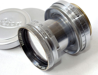
Before WWII, an old German
aperture scale could be used instead.
It was defined backward from a tiny aperture exactly equal to f/100.
The First Type of German aperture scale disappeared after WWII
1.1
1.6
2.2
3.2
4.5
6.3
9
12.5
18
25
36
50
71
100
The first of those abbreviations can be found in the second line of our
first table, which means that they represent apertures
located very nearly 1/3 of a step above a modern full stop. In practice,
that's good enough to use such lenses successfully with modern external light-meters.
To compute the precise difference between the two scales, let's divide by 100 the exact
value of the counterpart of f/100 in our modern scale:
2 20/3 / 100 = 1.0159366732596476638410916...
Thus, apertures in the old German scale are about 1.6% larger than their matching modern
counterparts. (they let in about 3.2% more light).
The difference is utterly negligible. It corresponds to 1/22 of an f-stop,
which is about half of the smallest aperture unit
(1/12 of an f-stop) used by digital cameras for internal computations.
Leitz Summitar f = 5cm 1:2 M39 Leica mount
Made in 1946, this is a rare example of a post-war lens using the old German aperture scale.
Photo courtesy of
Nettax, Sweden
As opposed to the current full-stop aperture scale, which was called international,
the obsolete one was variously called European, German or continental.
(2016-12-20) Lens Mounts
The standard ways a lens can be designed to match a camera body.
The flange distance (FFD)
of a camera mount is the distance from the focal plane to the outermost flat flange around the camera's
throat (which mates with the rear flange near the back of all compatible interchangeable lenses).
Thread Mounts :
The FFD of T-mounts is 55 mm, which is greater than the FFD
of the proprietary mounts of all major manufacturers of SLR 35 mm cameras (see below).
Thus, manual T-mount lenses can be adapted to all proprietary mounts.
The mini T-mount (M37, 0.75 mm thread) was released by Tamron (Taisei)
in 1957. It's now abandoned in favor of the
standard T-mount (M42, 0.75 mm thread) introduced in 1962 and still popular
for third-party optics, as adapters are cheap (the screw-in design of T-mounts only allows
manual lenses, as no electrical or mechanical connection is possible between the lens and the body).
The M42 introduced by the East-German branch of Zeiss in 1949 (Contax, Pentacon)
is incompatible with the T-mount because it has a different thread (1 mm).
It became known as the Praktica Thread Mount or the
Pentax Thread Mount.
It has a fairly short flange distance of 45.5 mm.
C-mount was the de-facto standard for
16 mm movie cameras. It features a flange distance of 0.69''
(17.526 mm) and 1'' mouth (25.4 mm)
with 32 threads per inch (i.e., 0.79375 mm pitch).
The C-mount originated around 1929 as an evolution of the A-mount and B-mount previously
used by Bell & Howell
(the C-mount was first found on their Filmo 70 cameras with serial numbers 54090 and above).
Bayonet Mounts :
Nikon's famous F-mount (three-lug bayonet)
was introduced in 1959. It has a flange distance of 46.5 mm and a throat
with a diameter of 44 mm.
The flange distance of Canon mounts is shorter than that. For the old Canon FD-mount (1971-1992)
it was only 42 mm.
The current Canon EF-mount (EOS, introduced in 1987) has a flange distance of 44 mm.
It's thus possible to make mechanical adapters to fit Nikon lenses on Canon bodies, but not the other way around.
The Micro Four-Thirds system (MFT or M4/3)
was introduced
by Olympus and Panasonic in August 2008, for mirrorless cameras with interchangeable lenses.
Its bayonet mount has a throat of 38 mm and a flange distance of 19.25 mm
(that allows recessed adapters for C-mount lenses, although vignetting will occur).
The image area of an M4/3 sensor has a nominal diagonal of 21.6 mm
(so, its crop factor is very close to 2).
For that format, the M4/3 standard replaced the previous
Four-Thirds system
by the same growing consortium (they kept the same logo).
To accommodate the mirror box of a DSLR they had a substantial flange distance
(38.67 mm) which proved too bulky for the mirrorless market.
The Sony E-Mount has a flange distance of 18 mm and a 46.1 mm throat.
(2016-12-20) Screw-on filter threads (diameter & pitch):
Mechanical specifications for mounting accessories on the front of a lens.
Screw-on photographic filters are rounds optical elements without any curvature
(they consist ideally of a flat plate of uniform thickness).
They are normally used either for their spectral response (colored filter,
cut filters)
or for their ability to block one particular polarization of light
(polarizing filter). They may also reduce the incoming light when a longer exposure
is desired (neutral density filters).
Large-format photographers employ expensive filters to correct the vignetting of
their wide-angle lenses (center filters,
dark near the center and clear near the rim).
Some other types of graduated filters
can either produce artistic effects or prevent the overexposure of skies.
The (female) filter thread at the front of a lens can also be used to attach various
accessories, including hoods,
close-up lenses, inverted lenses, carved grids (to produce diffraction stars),
irregular surfaces (for soft-focus), molded prisms (for multiple images),
split or drilled-out lenses, etc.
In addition to a male thread, most filters have a female thread on the opposite side,
so several filters can be stacked (this is a good way to store them,
but using several filters at once isn't recommended).
The pitch of a screw-on filter depends mostly on its diameter, according to the following
table. However,
it seems that the normal pitch of 0.75 mm
is also used for smaller diameters and larger diameters.
In the later case, the suffix c (coarse) can be
used to specify 1 mm pitch unambiguously.
Three pitches are commercially available for screw-on photographic filters
Thus, a transmittance of 25% ( ¼ ) corresponds to the following density:
log ( 1 / 0.25 ) = log (4) = 0.60206
Using the usual approximation of 0.3 for
the common logarithm of 2, this is always quoted as
a density of 0.6.
Several identifications are used for such a filter by different manufacturers, namely:
"ND 0.6" because the optical density is 0.6
(Kodak, Tiffen, Lee).
"102" or "2 BL" (B+W) since light is blocked by 2 f-stops.
"ND4", "NDx4" (Hoya)
or 4x (Leica). Factor of 4 in shutter speed.
B+W (owned by Schneider-Kreuznach since 1985)
now goes to the trouble of printing up to 4 markings (of all 3 above types).
For example, the ring of their (52 mm millimeter diameter) filter with 0.1% transmission reads:
B+W 52 110 ND 3.0 - 10 BL 1000x E
Most manufacturers aren't this redundant.
Normally, the clear differences in the above formats are sufficient to avoid ambiguities.
However, the very common NDx2 and NDx4 filters
(one and two stops, respectively) are often advertised as ND2 and ND4, which has
confused
some mail-order buyers looking for rare ND 2.0 or
ND 4.0 dark filters (NDx100 and NDx10000 respectively; 6.6 and 13.3 f-stops).
Typical markings on neutral-density filters for a given transmittance (%)
50%
25%
12.5%
6.25%
3.125%
1.56%
1%
0.78%
ND 0.3
ND 0.6
ND 0.9
ND 1.2
ND 1.5
ND 1.8
ND 2.0
ND 2.1
101
102
103
104
105
106
107
x2
x4
x8
x16
x32
x64
x100
x128
ND2
ND4
ND8
ND16
ND32
ND64
The list goes on with a few very opaque filters like
ND 2.6 = x400 (0.25% transmittance = 8.6 stops).
ND500 is also found.
Such opacities are close to the practical upper limit of what can be
obtained with optical faders (variable filters consisting
of two stacked polarizers).
One stop beyond that is the popular Big Stopper (or Big Blocker)
10-stop filter (0.1% transmittance)
which can be marked ND 3.0, 110, 10 BL
or x1000 (instead of x1024).
Such extremely opaque filters allow tripod shots at low shutter speeds in bright conditions,
so that waterfalls or foliage are just a blur in broad daylight...
Even more opaque filters are sporadically available,
mostly in the square 100mm by 100mm format
(4" by 4") from Lee, Kodak (Wratten) and others,
which is often referred to as "Cokin Z Pro".
You may occasionally find the following denominations, almost extinct:
x4000 or ND3.6 (12 stops, rarely called "112").
x10000 or ND4.0 (13.3 stops, for which "113" is a bit abusive).
Eclipse
filters for photographing the Sun (20 stops; ND6.0).
It's dangerous to use such filters for optical viewing of the Sun,
because a dilated pupil may let in too much damaging UV light.
The market for those tends to be rather small and prices can be prohibitive.
Square gels sometimes sell for $100 or more.
(2018-32-20) Photographing the Sun
What does it take to properly photograph the solar disk?
Cautious planning first and foremost. If you want to replicate the feat
described below, make sure you know what you're doing.
Aiming carelessly at the Sun with or without optics may damage your vision.
This is not a tutorial!
This is so much out of the realm of everyday experience that we need
some back-of-the-envelope calculations to get an idea of what the proper
exposure is:
The solar disk and the full moon have roughly the same apparent diameter
(or else we wouldn't have total solar eclipses lasting for just a couple of minutes).
That's about 0.52°. A better number is given by modern
astronomical data, provided by NASA.
Now,
consider a perfectly white object illuminated by direct sunlight.
By definition, it gives back all the luminous energy it receives in all directions
proportionally to its apparent area
in that direction For a tiny surface element, that apparent area is just
the surface area multiplied into the cosine of the angle of observation
q.
The total energy radiated back into the entire hemisphere is thus given by the
following expression, where I0 is the intensity radiated
per unit of solid angle perpendicularly to the element's surface.
I0 cos q dW
=
I0 cos q
sin q dq
If the light from the solar disk was spread out over the
solid angle of one hemisphere,
it would be correctly exposed according to the sunny 16 rule.
The solar disk subtends a solid angle about four hundred times
smaller, which would mean that there's a difference of about 18 stops
between a sunlit surface and the apparent surface of the sun.
With a 10-stop ND3.0 filter, you still need to expose 8 stops
below what the Sunny-16 rule says. Using 100 ISO and 1/4000 s
places us 5.3 stops below the Sunny-16 rule. If we stop down to
f/32, we're still overexposing, but not by much. That would be
within a stop or so from the correct exposure at which the Sun is no longer
just a white disk!
In such a photograph, the color balance must be manually set to
direct sunlight (5600 K). It clearly doesn't get
more direct than this!
Actually, a photo of the solar disk is a good check of the
color calibration of a camera.
The solar disk is the brightest object accessible to ordinary photography.
Lightning bolts are brighter but have smaller width.
Atmospheric nuclear explosions are brighter and wider.
(2015-05-30) Cut Filters
Selecting only part of the IR, visible and UV spectra.
The best known and cheapest ones are the mass-produced "UV filters" (L37) which photographers
often purchase as sacrificial glass to provide mechanical protection for
the front elements of their expensive lenses.
Hoya optical glass is transparent until 2700 nm or so,
at which point the transmittance falls sharply to reach 50%
at 2750 nm.
Then, there's a hills-and-valleys decrease until perfect opacity
is reached around 4500 nm.
Newcomer Zomei of Hong-Kong
(Xuzhou Bingo Network Technology Co., Ltd., mainland China)
uses RoHS-compliant HD glass from Schott.
Equivalences Between Some Common Longpass Infrared Filters
Proper infra-red photography produces an actual image of what the unaided
human eye can't possibly see.
That point is lost on those who use touch-up software to produce fake infrared look-alikes
from very ordinary pictures.
A color sensor behind an infrared filter may behave in unpredictable ways by
capturing some residual color information. Some amateurs have managed
to use that as the sole basis for beautiful false-color renditions...
That endeavor creates a dubious temptation to use sub-standard IR filters
(665 nm or 590 nm) instead of a proper 720 nm cut-filter.
As more visible light is allowed in, the hope is that more color information
will remain which might be usable...
That's a bad idea, because this practice is very likely to overwhelm the red
channel and silence the other two.
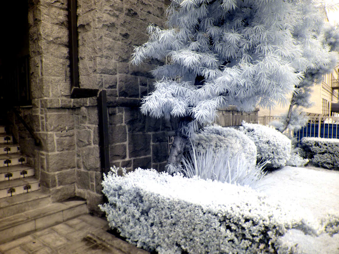
The picture below was taken in overcast weather at noon (June 2015, Los Angeles)
through a 720 nm filter (100% "de-fading" in post-processing).
If you want real false-color infrared images, bite the bullet
and make three separate exposures of the same subject through at least three different proper
infrared filters (720 nm or longer).
With the monochrome pictures so obtained, you may separate the infrared spectrum
into several channels by subtracting from every exposure the one taken with the next
filter (for the last channel, corresponding to your longest wavelength,
there's nothing to subtract).
Assign to each channel a visible color of your choice before combining
everything into a single picture.
(2015-05-21) Color temperature, tint and white balance.
Direct sunlight is 5200 K (not 5800 K). Shadows are 8000 K.
The average temperature at the surface of the Sun is 5778 K.
In the main, our star radiates like a blackbody at that temperature,
but there are thousands of dark Fraunhofer lines in the
solar spectrum. The most prominent of these were
first observed by Joseph von Fraunhofer
(1787-1826) in 1814.
(That great discovery is utterly irrelevant to photography.)
The atmosphere brings another level of complexity to sunlight, because
Rayleigh scattering is more pronounced for short-wavelength light.
Blue light is thus removed from direct sun rays and becomes visible in other directions.
Yes, that's what makes the sky blue and the Sun yellow
(or even red at sunrise/sunset, when
the rays have to travel through a greater distance through the atmospheric shell).
This effectively lowers the color temperature of direct sunlight
down to about 5200 K for the better part of the day.
Conversely, shady areas on cloudless days are predominantly lit by the blue sky,
which corresponds to a much higher color temperature (8000 K).
White clouds are lit from a combination of direct sunlight and skylight
which essentially yields back the same color temperature as sunlight outside
the atmosphere (5800 K or so).
When the Sun is behind clouds but some patches of blue sky are showing,
the resulting daylight has a typical color temperature of 6000 K.
6503.6 K is the correlated color temperature (CCT)
of the standard illuminantD65
defined by the CIE in 1967 and corresponding to average cloud conditions
over Northern Europe. It was originally just a crude estimate of
6500 K but a recalibration of the c2 radiation
constant in Planck's law (1968) introduced a correction factor of 1.4388 / 1.438
which now stands. The CCT of the D65 illuminant is often quoted as 6504 K.
Because the surface of the Moon better reflects red than blue,
the color temperature of moonlight is about 4150 K.
If the Moon is low on the the horizon, the color temperature of moonlight
can be much lower.
The color temperature of candlelight is around 1850 K.
Incandescent light (as invented by Edison)
is produced by a solid filament of tungsten,
which melts at 3422 C (3695 K; the highest melting point of any metal).
Therefore, no unfiltered incandescent light can possibly have a color temperature
greater than 3695 K.
(That's actually the color temperature of the bright flash emitted by
a dying incandescent bulb, since its imminent failure is due to the melting
of the filament.)
Ordinary incandescent bulbs are 2400 K or 2550 K ("soft white").
Studio photofloods are typically 3200 K (or up to 3400
for survolted ones). 3200 K is thus known to
old-school photographers as tungsten light.
Fluorescent light is entirely different because it's not produced by radiation from a hot body.
Traditional light tubes contain mercury vapor and the light they produce is
from the dominant light frequencies in the emission spectrum of mercury.
To a trichromatic sensor, like a normal human eye or a standard color camera,
this translates into a green tint; a color correction (CC) of +7, as explained in the next section.
Tint, Color Correction (CC)
Color Rendering Index (CRI)
The highest possible CRI of 100 is that of a perfect blackbody, at any temperature.
(2018-02-21) Measuring the color and darkness of all shadows.
One snapshot will tell how dark and how blue it really is in the shade...
To avoid light emitted into the shadows by anything other than the sky,
it's important to experiment away from buildings, trees, cliffs or any
object above ground level except yourself.
On a cloudless day,
put a large grey card on the ground (a calibrated 18% grey card is best but any white
sheet of paper will do; two smaller cards are even better than a large one).
Set the white balance of your camera manually
to direct sunlight (5600 K or so).
Cover part of the card with your own shadow and take
a properly exposed picture (making sure that the unshaded part of the card is
not overexposed).
The main source of inaccuracy in that procedure is the fact that your body masks part
of the sky and that it reflects a different kind of light onto the test card.
To minimize that, you could set the camera by itself on a tripod
(remotely operated or on a time delay and use just the camera itself to cast a small shadow).
Analyze the picture numerically and draw the conclusions.
In the nineteenth century that impressionists like
Auguste Renoir (1841-1919)
and Claude Monet (1840-1926)
started to paint the shaded part of sunlit scenes with bluish tints.
Before that, artists were just rendering shadows darker than the sunlit parts.
Breaking away from that tradition was quite a revolution in the art world.
The effect is very real but it went largely unnoticed until that time only because
the human eye compensates for it.
(2015-06-09) Color-conversion filters (CTR and CTB filters)
Converting one type of color balance to another.
This type of filters has been made all but obsolete by the "white balance" setting
of modern digital cameras. They survive in the form of gels
which you can put in front of additional light sources to balance them with existing light.
On the other hand, if you're shooting color film,
you may need filters in front of your camera
to match the loaded film with a type of light source different from the one specified by the film manufacturer.
That's especially so with color slides, which lack the flexibility of applying color correction at printing time.
The traditional Wratten numbers are just reference numbers which are not
based on any particular piece of information.
(The system was conceived well before fluorescent lighting existed and Kodak/Tiffen
extended it with two trademarked mnemonics later.)
By contrast, the Hoya numbers correspond to differences between the "milred" ratings of
the color temperatures involved ("micro reciprocal degrees").
The sign of that difference is specified either by an "A" for amber
or a "B" for blue. Thus, the numerical rating for their conversion
between the two common types of tungsten light is:
The first five filters listed above were commonly carried by most serious photographers
in the film era. They can be stacked.
For example, an FL-B filter is equivalent
to an FL-D stacked with an 85b (except that the latter combination is darker).
(2015-05-10) Flash photography
The guide number (GN) is defined in distance units, assuming ISO 100.
When a light source emits a pulse of luminous energy in the direction of a object at
distance d, each unit of surface of the object (measured perpendicularly
to the direction of a light ray) receives an amount of light (luminous energy)
inversely proportional to the square of the distance d.
On the other hand, the sensor of a camera observing an object at distance d'
receives from it an amount of light proportional to the square of its relative aperture.
If the light source is a flash unit mounted on the camera,
the distances d and d'
are approximately equal.
As d varies, for the sensor to receive the same amount of light
(inversely proportional to its sensitivity measured in ISO units)
the product of the aperture into the distance must be a constant,
called guide number.
Since the relative aperture is a dimensionless number, the guide number
has the dimension of a distance and is expressed in the same units as d.
The more powerful the flash, the greater the guide number.
The above relationships of proportionality can be expressed by the following
formula involving a universal constant S with the dimension of a surface area,
and actually proportional to the luminous energy of a flash pulse.
S / (ISO) = (guide number)2 = (distance x aperture)
For example, Nikon's
SB-500
has a GN (at 100 ISO) of 24 m (or
78.74 ft, rounded to 79 ft).
In metric countries, the unit of distance is often omitted (as it's understood
that photographers ought to measure distances in meters).
Knowing that the guide number is proportional to the square root of the ISO,
we may tabulate it for various sensitivities:
Guide numbers (GN) of Nikon's SB-500 Speedlight for different ISO sensitivities :
ISO
64
80
100
125
160
200
250
320
400
500
640
800
1000
1250
1600
GN
19
21
24
27
30
34
38
43
48
54
60
68
76
86
96
To double the GN for a given flash,
we must multiply the ISO by 4.
Nikon says that the built-in flash
of the D5500 DSLR has a standard
guide number (at ISO 100) of 12 m.
So, the SB-500 is 4 times more powerful.
The beam width of a flash unit is often given in term of the
focal length f of the widest lens whose field of view it would cover
for a full-frame sensor (24 mm by 36 mm).
Using the theorem of Pythagoras,
the diagonal of a full-frame is do = 43.2666153...mm
(or nearly 649/15).
Therefore, the
angular diameter q of the beam is given by:
½ do/ f
= t =
tan ( q/2)
or
q = 2 atan ( ½ do/ f )
Thus, in the case of the aforementioned Nikon SB-500 AF Speedlight,
the manufacturer specification f = 24 mm, translates into:
q = 2 atan ( 21.6333 / f )
= 1.467 = 84°
Focused Flash Beams :
Flash units with zoom heads
have several settings which can be selected either
manually or automatically to match the angular field-of-view of
the lens used by the camera. The automatic selection, involving a motorized
optical system, is very useful when the flash is mounted on a camera with a zoom lens.
For a given source, if we let the angle q vary
the luminous energy received by an object within the focused beam
is inversely proportional to the above solid angle W
of the bean.
This can be used to derive the guide number
at any zoom-head setting from the manufacturer's rating at
the narrowest one (in bold below).
Examples of Guide Numbers (GN) at ISO 100,
in meters or feet.
Beamwidth Setting
f
24 mm
28 mm
35 mm
50 mm
70 mm
85 mm
105 mm
q
96°
75.4°
63.4°
46.8°
34.3°
28.6°
23.3°
$125
Yongnuo YN568EX
28 m 92 ft
30 m 98 ft
39 m 128 ft
42 m 138 ft
50 m 164 ft
53 m 174 ft
58 m 190 ft
$380
Canon 580EX II
28 m 92 ft
30 m 98 ft
n/a
42 m 138 ft
50 m 164 ft
53 m 174 ft
58 m 190 ft
$200
Nikon SB-500
24 m 79 ft
No zoom head.
Nikon D5500 built-in flash
12 m 39 ft
No zoom head.
Table based on manufacturer specifications.
Canon's 580EX II
not tested.
Diffusers :
There are two types of diffusers, which serve different purposes:
Transparent diffusers
just increase the angle of the beam
(for use with a wide-angle lens, if the flash unit is mounted on the camera).
Diffusion screens and light boxes
will, in addition to the above, increase the size of the light source
(which transparent diffusers don't change much) which will soften the
shadows created by the flashlight.
For example, when the built-in transparent diffuser of the YN568EX is used,
the zoom goes automatically to its widest (24 mm) position
and the unit's LCD displays a focal length of
14 mm, corresponding to a beam diameter of 114°,
as estimated by the manufacturer. The GN is then about 15 m.
Honeycomb Grids :
This is roughly the opposite of a diffuser.
A grid narrows the beam of light in a specific way;
the finer (and thicker) the grid, the narrower the beam.
This works mostly by eliminating slanted rays,
which have to undergo many imperfect reflections to go through the grid.
Flash Synchronization :
The first camera with a built-in flash socket, activated by the
shutter,
was introduced by Exakta, in 1935.
One mainstay of flash photography are small coaxial cables with
3.5 mm (1/8") male connectors at both ends, matching
PC sockets.
The abbreviation stands for
Prontor/Compur
and is named after two brands of camera shutters, made by two distinct
manufacturers of which Zeiss
was a major shareholder (Compur from 1951, and Prontor from 1953 forward).
The dimensions were standardized, as ISO 519, in
1974
and
1992.
Electrically, the connection is simply an open circuit when inactive and a short circuit when active.
Several synchronization signals were generated by mechanical cameras for different
flash technologies. All of them were implemented in the legendary Nikon F.
Only "X" synchronization survives today, to drive electronic flash units.
The first three modes listed below (now obsolete)
were designed for magnesium-burning bulbs, which reached their peaks a few milliseconds after ignition.
M (Medium). Active 20 ms before the shutter is fully open.
F (Fast). Active 5 ms before the shutter is fully open.
FP (Flat Peak). Long-burning bulbs designed for focal-plane shutters.
X (Xenon). Active as soon as the shutter is fully open.
Actually, the pulses of light emitted by modern Xenon tube are so short that they can
be emitted at any time the shutter is open. Doing it just before the shutter
closes is known as rear-curtain synchronization.
That approach allows the dim motion trail of a moving object to be captured
during a long exposure, ending with a sharp flash-lit image frozen in time.
AFP: Stroboscopic flashing for fast focal-plane shutters.
FP synchronization is often transliterated as focal plane.
The specialized FP bulbs provided a constant illumination
between the time when the front curtain
started and time when the rear curtain arrived. This way, every part of the film
received the same amount of light, even at high shutter speeds
(achieved by allowing only a small slit between the two moving curtains).
Nowadays, the equivalent of an FP bulb can achieved by strobing
an electronic flash very rapidly throughout the time the curtains travel.
This is called AFP (Auto FP) by Nikon and HSS
(High-Speed Sync.) by Canon.
AFP (HSS) solves a problem with no other solutions:
A poorly-lit fast-moving subject in front of a bright background.
A fast shutter is needed to freeze the motion (say t = 1/4000 s)
but a flash in the usual X-mode can't be used to light up the subject because
it the camera would then require a relatively slow shutter speed
(say T = 1/200 s) which would overexpose the background.
Another case is often quoted where a blurry background is desired
(hence wide aperture and fast shutter) with a static subject.
However, this can be captured without AFP
(using neutral density filters).
AFP (HSS) effectively uses only a fraction of the energy delivered
by the flash unit. That fraction is equal to the nominal exposure time
(t) divided by the time (T+t) during which stroboscopic
illumination must be maintained because part of the image sensor is exposed.
To compute the latter duration, we assume the flashes have negligible duration.
The time it takes for one curtain to travel the focal plane is then
seen to be equal to the shortest shutter time which ensure that the entire
sensor is exposed at once. This is a critical characteristic
of the camera which is well advertised as the fastest shutter speed at which
an electronic flash is usable with X-synchronization
(T = 1/200 s, in our example).
Now, "flat" illumination must be maintained between the departure of the
front curtain until the arrival of the rear curtain, which is roughly
the aforementioned duration T+t.
Each point of the sensor receives only a fraction
t / (t+T) of the total stroboscopic light emitted:
1 / (T/t + 1) = 1 / (4000/20 + 1) = 1 / 21
As every photographer who ever used this technique knows, it's thus very wasteful
in terms of luminous energy. In our numerical example,
the drain on the unit's battery is at least 21 times what would have
been required to properly expose the subject with a single strobe at low shutter speed.
If the frequency of the flash unit is an exact multiple of 1/t, then
the illumination will be perfectly uniform (regardless of the shape
of each pulse, assuming they are all alike).
Now, notice that all standard exposure times above 1/8000 s
in steps of half an f-stop are exact multiples of 1/24000.
So, if the unit delivers its pulses at a frequency of 24000 Hz,
that condition is met for any camera that aligns its shutter
speeds precisely at half-stops, using the nominal values:
Whole stops and half-stops exposure times as exact multiples of 1 ms / 24
3
4
6
8
12
16
24
32
48
64
96
1/8000
1/6000
1/4000
1/3000
1/2000
1/1500
1/1000
1/750
1/500
1/375
1/250
There's no need to go beyond that table, as the technique is utterly
useless when ordinary flash photography applies
(usually, at 1/200 s or slower).
On the other hand, if the unit's stroboscopic frequency is unrelated to the exposure time,
it must be large enough to ensure that every point is exposed to
an average number of flashes sufficient to make the contribution of
one extra pulse fairly irrelevant, in relative terms...
For example, if flash pulses at some frequency around 100 kHz
are used with a 1/8000 s exposure time,
each pixel sees between 12 and 13 pulses.
The maximum deviation from the
geometric mean of 12.49 is 4%,
which corresponds to the following peak-to-peak amplitude, measured in f-stops:
log 2 ( 13 / 12 ) = 0.115477...
(about 1/9 of an f-stop)
The resulting light-and-dark bands are barely detectable.
Still, for AFP/HSS
photography, it's a good idea to use stroboscopic light at 24 kHz
(or a multiple thereof) to take advantage of the above numerical remark...
If 96 kHz is chosen, there's no banding in 75% of the choices
of standard shutter speeds (including 1/8000 s and 1/6400 s).
The worst banding is for 1/5000 s,
if you absolutely insist on that shutter speed:
log 2 ( 20 / 19 ) = 0.074
(about 7.4% of an f-stop)
If the clock of the camera and the clock of the flash unit are slightly off,
low-contrast bands are indeed produced, but they are much too wide to be noticed
(wider than the picture itself, for crystal-controlled clocks).
Focal-plan shutters.
Rear-curtain sync.
Auto focal-plane (AFP) = HSS sync.

")
")